› Forum › Digital source › SPDIF output
- This topic has 12 replies, 2 voices, and was last updated 1 year, 3 months ago by
 The Well Audio.
-
AuthorPosts
-
-
18/03/2023 at 11:47 #2327
jmmbarco
ParticipantHi Andrea!
I want to try getting a spdif out from the FIFO Lite. Is there any chance you design an spdif interface that could be driven from thge FIFO?. In case not, what would you recommend? I am considering IANs mk2 transport as it could be drive from the MCLK output of the FIFO. What do you think?
-
18/03/2023 at 12:41 #2328
 The Well AudioParticipant
The problem is that SPDIF is a very jittery interface by itself, since the clock is embedded in data.
So that, there will be a PLL after the SPDIF receiver, which practically vanishes the help of the FIFO.
That’s the reason we have not implemented SPDIF output in the FIFO.
SPDIF will be an input for the FIFO, since in the future we will design a SPDIF-I2S interface, but not an output.We like to be honest, so we cannot incourage such way, because the SPDIF shouln’t be used to get good performance.
About the tantalum nitride version of the DAC Lite I understand your frustration, but keep in mind that we cannot test all the ways when we develop a device. Developing cost are huge, so we have to make some design choices at the beginning.
We have discovered the TN resistors when we tested the DSD DAC because a user suggested to try them. Then we also have built a TN version of the DAC Lite.
It sounds a little more detailed with TN resistors, but it’s a small difference, the standard DAC Lite sounds already very well.
Hope you undertand. -
19/03/2023 at 00:42 #2329Participant
The fact is that my ABBAS DAC is only spdif input and I want to keep it. So I want to build the best diy interface for it. I would prefer to integrate your FIFO into the ABBAS DAC but I do not dare to do this mod…So please let me ask you again for the combination of your FIFO with IANs spdif, can you think about any reason why it shouldn`t work? any better chance you can imagine?
As for your DAC I have almost decided to wait for your SOTA DAC.
-
19/03/2023 at 00:58 #2331The Well AudioParticipant
Since TRANSPORTPI MKII accepts I2S input it should work. There is also a MCK input but I don’t know what frequency is suitable for this input, you should ask the designer. BTW, the FIFO Lite provides MCK output at the frequency of the connected oscillators.
We are working on the Sonic Empire DAC but it will take long time to get it ready, at least one year, maybe more.
In the meantime I would suggest to get the DAC Lite running and compare it with your ABBAS DAC driven by Ian’s SPDIF transport.
-
27/03/2023 at 19:10 #2354Participant
Dear Andrea,
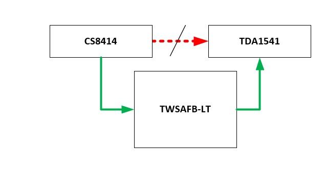
I have thought about another possibilty and I would like to know your opinion. My DAC is basically CS8414 into TDA1541a in NOS mode. I mean, there is no SAA72xx in the layout.
Assuming CS8414 outputs I2s into the TDA, I could “break” this conection and route 8414 output into the input of the FIFO and the output of the FIFO into the TDA. would this work?
-
This reply was modified 1 year, 4 months ago by
jmmbarco.
-
This reply was modified 1 year, 4 months ago by
 Moderator.
-
This reply was modified 1 year, 4 months ago by
-
27/03/2023 at 22:31 #2357The Well AudioParticipant
Yes, it should works.
-
24/04/2023 at 19:21 #2389Participant
Hi again Andrea,
This weekend I have build a cheap TDA1541a DAC and a test PSU for the TWSAFB-LT. Both are working fine.
Before testing the above diagram I was wondering wether a ground loop could be created as I am connecting the TDA GND to the input but also to the output of the FIFO….
Thanksin advance for your support! :))
-
This reply was modified 1 year, 3 months ago by
Attachments:
You must be logged in to view attached files. -
This reply was modified 1 year, 3 months ago by
-
24/04/2023 at 23:33 #2392The Well AudioParticipant
You should connect the ground of the TDA to the output of the FIFO only.
-
25/04/2023 at 14:24 #2393Participant
Sorry Andrea for re-asking but I am confused, do you mean that, in my specific schema, it is only necessary to connect to the input of the FIFO LRCK, BCK and DATA leaving GND pins unconnected?
Is this because the CS8414 and the TDA share the same GND and it is already connected at the output of the FIFO?
-
25/04/2023 at 17:50 #2394The Well AudioParticipant
If possible you should break the ground sharing between CS8414 and TDA.
-
25/04/2023 at 19:29 #2395Participant
I do not see how this is possible. I am sure I am not explaining myself correctly…
What I am in fact doing in this test is:
1. I am pulling out the TDA from its socket and installing a smalll permaproto (lower one) with a double row pin header into all 28 pins.
2. Above this permaproto I install a second identical permaproto (upper one), just 5mm above. All pins are connected between the two permaprotos excepting PINs 1, 2 and 3.
3. I install the TDA on the upper proto in the same position as in the socket.
3. PINS 1,2 and 3 of the lower proto (XH connector) are connected to the input of the FIFO, carrying the signals coming from the CS8414.
4. PINS 1,2, and 3 of the upper proto(XH connector) are connected to the output of the FIFO, carrying the signals “reclocked” into the TDA.
What I am asking, if possible, is how and where to connect GND in this scenario.
Maybe using an I2S isolator between the lower proto and the FIFO input?
-
This reply was modified 1 year, 3 months ago by
-
This reply was modified 1 year, 3 months ago by
-
26/04/2023 at 10:21 #2397The Well AudioParticipant
If you cannot break the ground sharing between CS8414 and TDA1541A you are at risk of a ground loop.
You can try connecting both FIFO ground (input and output) close to the TDA1541A, as in the picture you have uploaded.
Not sure this will avoid ground loop.
-
-
AuthorPosts
- You must be logged in to reply to this topic.